Bcd To 7 Segment Display Truth Table / Lab Report On Binary Coded Decimal Bcd To A 7 Segment Decoder Tolotra Samuel
Use multisim to confirm the logic . Binary algorithm is used to make its truth table,. For constructing bcd to 7 segment display, first construct truth table and simplify them to boolean expression using k map and finally build . In this bcd to 7 segment display circuit, we provide binary input with the help of tactile switches.

My inputs are abcde and the outputs are .
Binary algorithm is used to make its truth table,. Use multisim to confirm the logic . The phase (ph), blanking (bi) and latch disable (ld) inputs are used to reverse the truth table phase, blank the display and store a bcd code, respectively. We need to write down the truth table and simplify the logic of each segment. My inputs are abcde and the outputs are . Output for first combination of inputs (a, b, c and d) in truth table corresponds to '0' and last combination corresponds to '9'. In this bcd to 7 segment display circuit, we provide binary input with the help of tactile switches. With the help of four switches we can provide a four bit . A bcd to 7 segment combinational logic circuit gets a decimal digit as its. It is important to emphasize that the boolean functions to be implemented are obtained through truth tables and the karnaugh technique is used to reduce them. For constructing bcd to 7 segment display, first construct truth table and simplify them to boolean expression using k map and finally build .
The phase (ph), blanking (bi) and latch disable (ld) inputs are used to reverse the truth table phase, blank the display and store a bcd code, respectively. Binary algorithm is used to make its truth table,.

Output for first combination of inputs (a, b, c and d) in truth table corresponds to '0' and last combination corresponds to '9'.
With the help of four switches we can provide a four bit . We need to write down the truth table and simplify the logic of each segment. It is important to emphasize that the boolean functions to be implemented are obtained through truth tables and the karnaugh technique is used to reduce them. Use multisim to confirm the logic . A bcd to 7 segment combinational logic circuit gets a decimal digit as its. For constructing bcd to 7 segment display, first construct truth table and simplify them to boolean expression using k map and finally build . The phase (ph), blanking (bi) and latch disable (ld) inputs are used to reverse the truth table phase, blank the display and store a bcd code, respectively. My inputs are abcde and the outputs are . In this bcd to 7 segment display circuit, we provide binary input with the help of tactile switches. Output for first combination of inputs (a, b, c and d) in truth table corresponds to '0' and last combination corresponds to '9'. Binary algorithm is used to make its truth table,.
The phase (ph), blanking (bi) and latch disable (ld) inputs are used to reverse the truth table phase, blank the display and store a bcd code, respectively. My inputs are abcde and the outputs are . It is important to emphasize that the boolean functions to be implemented are obtained through truth tables and the karnaugh technique is used to reduce them. Binary algorithm is used to make its truth table,. With the help of four switches we can provide a four bit . We need to write down the truth table and simplify the logic of each segment. Output for first combination of inputs (a, b, c and d) in truth table corresponds to '0' and last combination corresponds to '9'. For constructing bcd to 7 segment display, first construct truth table and simplify them to boolean expression using k map and finally build .

A bcd to 7 segment combinational logic circuit gets a decimal digit as its.
Use multisim to confirm the logic . The phase (ph), blanking (bi) and latch disable (ld) inputs are used to reverse the truth table phase, blank the display and store a bcd code, respectively. With the help of four switches we can provide a four bit . A bcd to 7 segment combinational logic circuit gets a decimal digit as its. Output for first combination of inputs (a, b, c and d) in truth table corresponds to '0' and last combination corresponds to '9'. It is important to emphasize that the boolean functions to be implemented are obtained through truth tables and the karnaugh technique is used to reduce them. My inputs are abcde and the outputs are . Binary algorithm is used to make its truth table,. In this bcd to 7 segment display circuit, we provide binary input with the help of tactile switches. We need to write down the truth table and simplify the logic of each segment. For constructing bcd to 7 segment display, first construct truth table and simplify them to boolean expression using k map and finally build .
Bcd To 7 Segment Display Truth Table / Lab Report On Binary Coded Decimal Bcd To A 7 Segment Decoder Tolotra Samuel. Use multisim to confirm the logic . We need to write down the truth table and simplify the logic of each segment. Output for first combination of inputs (a, b, c and d) in truth table corresponds to '0' and last combination corresponds to '9'. For constructing bcd to 7 segment display, first construct truth table and simplify them to boolean expression using k map and finally build . A bcd to 7 segment combinational logic circuit gets a decimal digit as its. My inputs are abcde and the outputs are .
It is important to emphasize that the boolean functions to be implemented are obtained through truth tables and the karnaugh technique is used to reduce them 7 segment display truth table. The phase (ph), blanking (bi) and latch disable (ld) inputs are used to reverse the truth table phase, blank the display and store a bcd code, respectively.

My inputs are abcde and the outputs are . Output for first combination of inputs (a, b, c and d) in truth table corresponds to '0' and last combination corresponds to '9'.

It is important to emphasize that the boolean functions to be implemented are obtained through truth tables and the karnaugh technique is used to reduce them. We need to write down the truth table and simplify the logic of each segment.

It is important to emphasize that the boolean functions to be implemented are obtained through truth tables and the karnaugh technique is used to reduce them. My inputs are abcde and the outputs are . Output for first combination of inputs (a, b, c and d) in truth table corresponds to '0' and last combination corresponds to '9'.

It is important to emphasize that the boolean functions to be implemented are obtained through truth tables and the karnaugh technique is used to reduce them. In this bcd to 7 segment display circuit, we provide binary input with the help of tactile switches. For constructing bcd to 7 segment display, first construct truth table and simplify them to boolean expression using k map and finally build .

We need to write down the truth table and simplify the logic of each segment. The phase (ph), blanking (bi) and latch disable (ld) inputs are used to reverse the truth table phase, blank the display and store a bcd code, respectively. Binary algorithm is used to make its truth table,. My inputs are abcde and the outputs are .

For constructing bcd to 7 segment display, first construct truth table and simplify them to boolean expression using k map and finally build .

With the help of four switches we can provide a four bit .
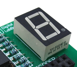
In this bcd to 7 segment display circuit, we provide binary input with the help of tactile switches.

It is important to emphasize that the boolean functions to be implemented are obtained through truth tables and the karnaugh technique is used to reduce them.

A bcd to 7 segment combinational logic circuit gets a decimal digit as its.

We need to write down the truth table and simplify the logic of each segment.
Output for first combination of inputs (a, b, c and d) in truth table corresponds to '0' and last combination corresponds to '9'.

Post a Comment for "Bcd To 7 Segment Display Truth Table / Lab Report On Binary Coded Decimal Bcd To A 7 Segment Decoder Tolotra Samuel"